Basic TX
m (grammar fixed) |
|
| (One intermediate revision by one user not shown) | |
Latest revision as of 13:15, 16 April 2020
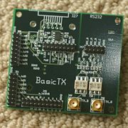
This USRP RF daughterboard take the signals from the D/A converters and provide the output with SMA connectors via transformers (2 output channels). It doesn't use any active components, what you get after the transformer is what you get from the D/A converter. This board can be used to drive an external quadrature modulator or to generate directly RF signals
The D/A converter of the USRP is at 128MHz so it is possible to generate frequencies up to 64MHz. However, because of the absence of filtering, there are harmonics centered around 128MHz and around 256MHz (and higher but components get much weaker). This is the reason why it is possible to generate signals in VHF bands.
For example to generate a signal at 225MHz, the baseband signal will be at 31 MHz and the harmonics at 128-31=97MHz; 128+31=159Mhz; 256-31=225MHz; 256+31=287MHz. Because we use a "soustractive" harmonic, the signal is mirrored so it is necessary to generate a mirrored baseband signal so that it have it corrected. This can be done by adding a "-" sign to the frequency argument in gnuradio or CRC-Dwap.py.
[edit] DAB tests with Basic TX
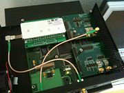
Test with the BasicTX: On the picture you see the board installed inside the USRP, TX A port (Upper right)
When we generate a signal on this board we have measured a total power of 18 uW. (with 50 ohm load 0 dB of gain in the gnuradio module)
As we use one DA from the TX A port (USRP have two DA's with balanced output on each port) we get a real signal at the output, meaning that you get every harmonics and image frequency till they go in the noise floor (bandwidth of the onboard transformer used to unbalance and adapt the output inpedance)
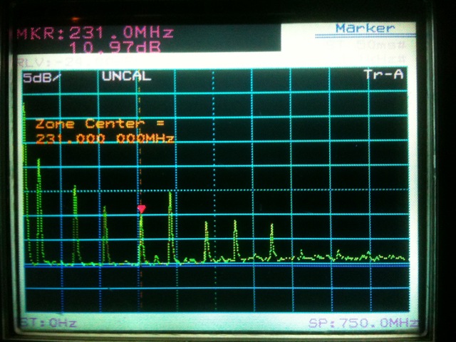
This is a typical output spectrum of the BasicTX.
Note the red marker showing the desired working frequency in the Band III (see Band 3 Channels) (exact value: 12C @227.360 Mhz during the measurement).
To filter the lower and stronger peaks will required more than 80 dB of attenuation and the same for the next upper peak ! The picture show the spectrum from 0 to 750 Mhz
So ! this will required further filtering before applying any pre amplifier stage...
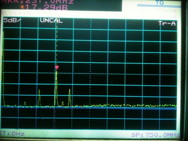
The same now but with a first filtering trial... we still have too much unwanted carriers near the working band !!! TBC...


