USRP B200 Measurements
Contents |
Measurements of the USRP B200
Setup
The ODR-mmbTools have been used to generate a DAB transmission with the B200, which was connected to a R&S spectrum analyser.
Versions used:
- ODR-DabMux v0.6.0
- ODR-DabMod v0.4.3
- UHD release_003_007_000
The USRP B200 was connected over USB2.0 to a thinkpad T420, and was externally powered using a 6V laboratory power source.
Measurements
All measurement data, parameter and spectrum plots are packaged together: B200-measurements.zip
The meas-parameters.csv file describes the dabmod parameters
- master_clock_rate
- sample rate
- gain mode
- digital gain
- analog TX gain
used for each generated image.
Observations
- digital gain* of 1.0 or *gain mode* 0 lead to spurious signals.
This can be due to clipping in the digital domain.
Some *master_clock_rate* settings are better than others. The decimation factor N = master_clock_rate/sample rate is the important parameters.
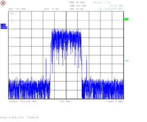
For N = 5 (10240000), 6 (12288000), 10 (20480000) and 15 (30720000), we see ugly shoulders next to the transmission.
For N = 8 (16384000), 12 (24576000) and 16 (32768000) the ugly shoulders are not present. N = 4 and below doesn't work.
The analog *TX gain* has to be above 35, but at about 80 we start seeing the shoulders increase. The best value for this parameter has to be found experimentally, in a complete transmitter setup, but is likely to be between 70 and 85.
Conclusion
The best settings seem to correspond to
- gain mode = 2
- master_clock_rate = 32768000
- native DAB sample rate of 2048000
- digital gain = 0.8
- tx gain at most 80
The effect of the FIRFilter still has to be measured.
A real world will certainly offer us more insight into these parameters.
Remarks from Ian (Ettus)
The above measurements were communicated to Ettus, and Ian kindly answered the following:
By design we aim to support a digital signal dynamic range of -1 <= x < 1 on all USRP's (which corresponds to integer values -32768 -> 32767 inside our transport over USB). In practice we always recommend leaving a small amount of headroom (i.e digital gain < 1.0). There is a know issue in B200/B210 where digital overflow occurs on transmit within this signal range, and this is scheduled for a bug fix in the next major public release (approximately 1 month from now). The 0.8 digital gain value you have empirically determined is a good value to proceed with until then.
"master_clock_rate" is used to configure the fractional-N synthesizers in the radio and thus there is great flexibility in targeting values that are exact integer multiples of your nominal application sample rate, which means that the optimum configuration of digital interpolation filters can be used to minimize spectral aliasing. As a general rule across all products in the USRP2 and USRP3 architectural families (USRP2/N2x0/E1x0/B1x0/B2x0/X3x0) we always recommend that the configured interpolation/decimation ratio be factorable by 4. This is because the internal USRP DSP signal chain is as follows (for Tx):
CIC Filter (interpolate by 2 through128)->Halfband FIRFilter (31tap - interpolate by 2)->Halfband FIR Filter (7tap - interpolate by 2)
When the interpolation ratio is factorable by 4, both half band filters are enabled and these offer the most optimal spectrum. The CIC filter offers great flexibility in available interpolate ratio's but has has poor stop band rejection when used in isolation. Thus, for example when you tested N=5/15 only the CIC filter was enabled, and with N=6/10 only one half bad filter was enabled in series with the CIC. N=8/12/16 enables both half band filters in series with the CIC and hence you saw improved spectrum.
With B2x0 however further optimization beyond this filter configuration is possible. This is because further programable digital and analog filter stages exist in the radio external to the FPGA. The total Tx signal chain of programable filters is thus:
CIC Filter -> Halfband Filter -> Halfband Filter -> FIR Filter (128tap interpolate by 1/2/4)->Halfband Filter->Halfband Filter->Halfband Filter OR CIC filter(interpolate by 3)->Analog filter->Analog filter
The digital filters in the radio are configured to target an optimal clock rate for the ADC within the radio, normally several hundreds of MHz. By choosing an optimal "master_clock_rate" you can ensure that the best combination of filters is used w.r.t output spectrum. Thus if I use your value of 2,048,000Hz as your nominal application sample rate, then I would recommend 8x this as the master_clock_rate (16,384,000Hz) which will cause the total digital filter chain to be configured as: CIC(int by 2)->HB(int by 2)->HB(int by 2)->FIR(int by 2)->HB(int by 2)->HB(int by 2)->HB(int by 2)->ADC(@~262MHz)
I see you had problems using values of N<4. This is likely due to you exceeding transport bandwidth, perhaps B200 was only connected as USB2? Values of N of 2 and 1 should also give good results and do work but are likely to require a transport of USB3 super speed due to the sample rates involved.
The "analog" Tx gain range is much larger on B2x0 than other USRP's due to features unique to the radio used. In common with all Ettus radio's we offer enough gain control that the analog amplifiers can be driven into compression and start to become non-linear. When that happens is combination of many factors including the signal you are applying as input. The gain value of 80 in your notes is approximately where we see many applications using the full input signal range begin to drive the analog stages into a non-linear range, and you will need to set this value as appropriate for your own application by observing the spectrum (as you have).
